One of the most enjoyable parts of electronics design is getting excellent performance with rock-bottom parts cost. The right circuit can produce exceptionally good speed, noise, and accuracy specs from very low-cost parts. A case in point was a project from December 2016: a time-domain reflectometer (TDR) for a liquid level sensing application in industry.
TDRs work by sending short pulses down a transmission line where they bounce off anything that disturbs their propagation. By measuring the time delay, you can tell how far down the line the disturbance is. It's a bit like a one-dimensional radar, except that with TDR you can learn a lot more from the reflection than just its location. TDRs can find damaged optical fibres, waterlogged sections of coax cable, and many other things of that sort. This application used an air-dielectric coaxial probe built from two metal tubes sticking downwards into a tank, so that the first part of the probe had air as dielectric and the second part had liquid. The dielectric constant of a liquid is at least 2, whereas air's is 1.0, so there's a nice healthy impedance mismatch at the surface to reflect the pulse. This approach is very rugged and resistant to fouling (you can get all sorts of nameless crud in process water and diesel tanks, for instance).
Simple TDRs use stroboscopic sampling: you generate a transmit pulse and a sampling pulse with a variable delay. The sampling pulse controls the sample gate, which measures the reflected pulse in a very brief time interval (tens to hundreds of picoseconds usually). You only get one measurement per pulse, so you measure one, slide the delay along a bit, measure the next, and so on until you build up a whole trace.
Another guy did the delay generator, back end digitizer, and all the secret sauce in the actual transducer design that ensured a nice clean reflection. My bit was the fast stuff: the pulse generators, sampling gate, and sample/hold amplifier. Commercial TDRs cost thousands of dollars, but this application is very price-sensitive; for a 100-ps-class sampler, my bill-of-materials budget was $2. Fun.
At that price, there was no way we were going to be using ECL comparators, custom matched diode sampling bridges, or 100-MHz op amps: it was one diode for the sampler, LVDS line receivers as comparators to generate fast steps, discrete microwave transistors to make them faster, and PCB trace stubs and very small capacitors to differentiate them into pulses. After that, there was an all-discrete amplifier and a single JFET track/hold to store the pulse before the sampling capacitor discharged. One half of a jellybean dual op amp buffered the output and another one looked after the fast amp's bias.
I apologize that I can't show the schematic for NDA reasons (it's somebody's new product, after all). Here are the SPICE simulation results for a delay range of 550 ps in 50-ps steps. Actual performance was comparable.
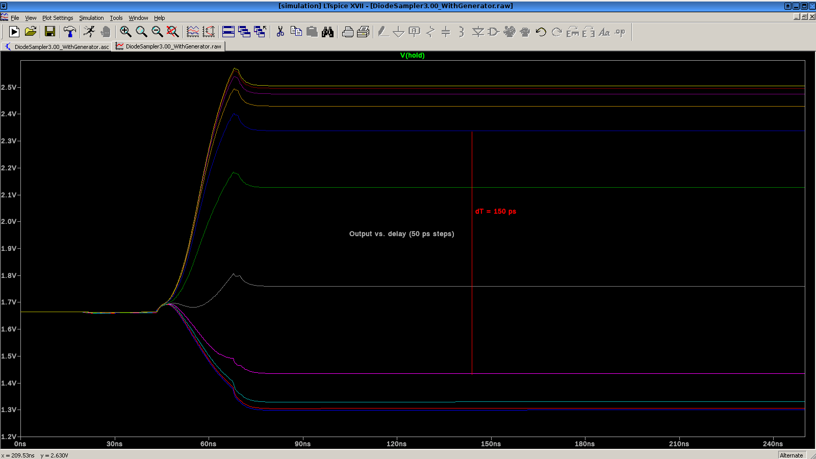
The two of us spent a couple of days in the lab here at EOI building a dead-bug prototype of the sampler. It uses all SOT23, SC-70, 0603, and a super small (0402ish) sampling diode. Connectors are MMCX to minimize pigtail inductance. It has a nice clean sampling response, 150-ps gate width (probably 100 ps FWHM), 17 ps p-p jitter, BOM cost $1.30 excluding connectors. I cheated slightly in the proto by replacing the BJT edge generators with pHEMTs--an extra 80 cents--to make up for the higher stray inductances, so it's really $2.10. The product uses BJTs, so we hit the BOM target with ease. A couple of parts went EOL, but were reasonably easy to replace, and the replacements were even cheaper.
Sampling resolution was limited by the voltage gain of the pHEMTs, because the line receivers produced about 1-ns edges, so it took awhile to turn the pHEMT all the way on. A couple of superfast ECL comparators such as ADCMP580 would have been several times quicker, but they cost about $13 each. For this job, our TDR's accuracy (plus or minus 1/4 inch) was easily good enough.
For the test, we used a Highland Technology Model P400 digital delay generator to do the timing. (Highland makes all kinds of great stuff for time-domain measurements.) We were pretty pleased by that 17 ps jitter number, especially since there was no shielding and a bunch of cell phones around. It's neat to be able to tune the delay by 10 ps and see the sampler output change.
Prototyping is sure slow when you're fighting the surface tension of the solder and the tendency of all of the midair solder joints to melt at once. 0603-pitch pad board with ground plane is a big win for this sort of job, but some of the hairiest mid-air things took 10 tries to get right, even under a Mantis stereo microscope.
The resulting product has been successfully introduced. (*)
Really a fun project.
Phil Hobbs
(*) The customer requested that the SPICE schematic and the names of the company and the other consultant not be used for this article. It's a good gizmo, anyway.