Silicon Photomultiplier (SiPM, MPPC) System for Cathodoluminescence
In How We Work, we gave an overview of how we build instruments, from the initial feasibility calculation (or photon budget) to delivery of the first production units.
Each project is different, of course, but there are common themes. Here's a description of these steps from our most recent one at this writing (late January 2020), which is a low-cost cathodoluminescence detection system for use in scanning electron microscopes (SEMs).
Photon Budget
Cathodoluminescence Principles
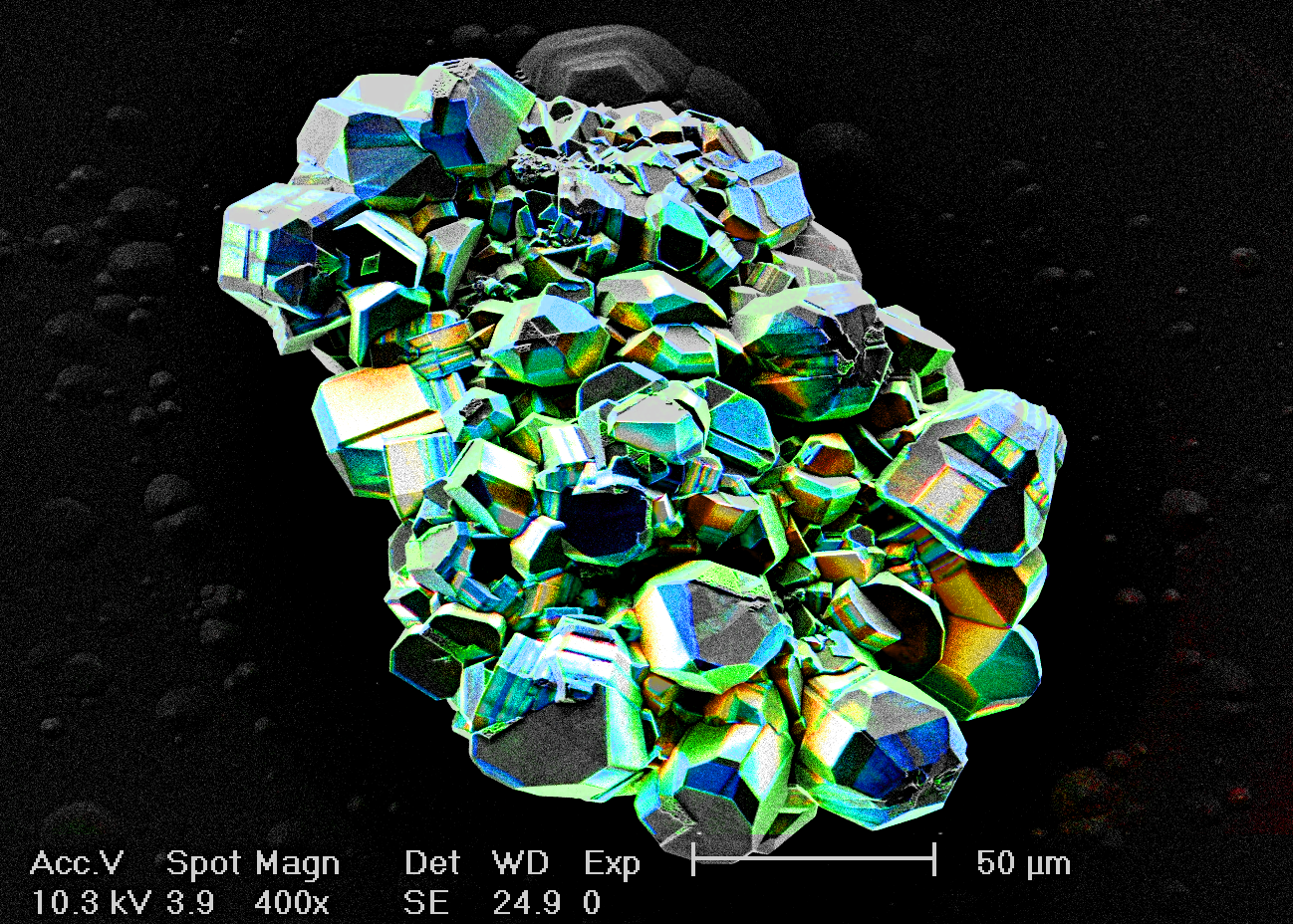
A SEM works by scanning a tightly-focused beam of high-energy electrons (1 keV - 30 keV) across a sample, and looking at the stuff that comes out. For ordinary imaging you usually look at backscattered and secondary electrons, but there are other modes. For instance, you can get a lot of information about the sample's chemical composition by looking at the x-rays it emits. Most samples will also emit some amount of light, a process called cathodoluminescence .
Of course, some samples are a great deal brighter than others. The luminescent yield is the average number of photons escaping from the surface of the sample per incident electron. It ranges from about 10-5 for some metals to more than 100 for LED chips.
Signal-To-Noise Ratio
To make a halfway decent image, you need a signal-to-noise ratio (SNR) of at least 20 dB, which means at least 100 detected photons per pixel on average. The smallest vaguely useful image size is around 300x300 pixels, so a minimally acceptable image needs at least 100×300×300 ~107 detected photons.
Good images, ones you might want to publish, would have 10 times that many pixels and would need 10 or even 100 times more photons per pixel to reduce the visual noise. To make the system pleasant to use, you want the frame time to be at most a few seconds during setup and no more than a minute for a high quality image. Thus we need a count rate ≳107e- / 3 s or 3 MHz for low SNR and ≳109 - 1010 e- / 60 s or 17-170 MHz for high quality.
A typical beam SEM beam current is on the order of 100 nA, which is roughly 1012 electrons per second. The total photon emission rate will thus be between 1010 and 1014 per second for our intended range of samples. Fancy cathodoluminescence systems use large ellipsoidal or parabolic mirrors to collect nearly all of the emitted light, but those are a huge pain to align, and they get in the way of the other detectors for secondary electrons and x-rays.
This low-cost system is intended to be inexpensive and easy to use. The client was willing to specialize it for somewhat brighter samples, those with yields of ~0.1% or higher. We therefore relied on putting the sensor as close as possible to the sample without running into anything or blocking other detectors.
The result was that we collect about 1% of the emitted light. With 35% peak overall efficiency (48% area efficiency and 72% detection probability), we have about 4×10⁷ to 4×10¹¹ detection events per second. With an ordinary photodiode with a gain of 1, that's a current range of about 6 pA to 60 nA, and that's for light near the peak sensitivity wavelength of the detector. It's hard to get good results in a wide bandwidth with that sort of current, so an electron-multiplying detector helps a lot.
Together with the client, we chose a tiled array of Hamamatsu multi-pixel photon counters (MPPCs), also known as silicon photomultipliers (SiPMs). These devices are sensitive to single photons, and have about the same overall quantum efficiency as a PMT (10-40% or so, depending on wavelength). They consist of an array of hundreds or thousands of individual avalanche photodiodes (APDs) wired in parallel, each with a series resistor to recharge it when it fires. At the right bias voltage, a single detected photon will cause one of these APD pixels to avalanche, dumping a fixed amount of charge into the external circuit. They recharge pretty fast (~20ns), which makes MPPCs useful in analogue mode as well as photon counting mode.
In Building Electro-Optical Systems I'm quite critical of avalanche photodiodes in general, because on an apples-to-apples basis they have around a million times higher dark count rates than photomultiplier tubes (PMTs). That is, a 100-μm silicon APD has about the same dark count rate as a four inch bialkali PMT. That's really bad for the lowest-light measurements.
MPPCs do have some very important advantages, though: they're much less delicate, easier to drive, longer-lived, and considerably cheaper. In this case that turned out to be a big win, because the minimum useful signal for imaging (3 MHz count rate) is more than three times the maximum dark count rate (about 900 kHz in our operating conditions). Thus for imaging, the dark count rate has only a minor effect on the system performance.
Proof of Concept
The POC prototype was composed of our high bandwidth voltage controlled amplifier (0.5×-64×, 50 MHz BW), low dissipation thermoelectric cooler (TEC) driver, and avalanche photodiode bias supply; a custom front end based on previous designs, with a bootstrap based on a Mini Circuits SAV-551+ pHEMT; a collection of power supplies out of the drawer; and of course a very nice Hamamatsu MPPC with built-in thermoelectric cooler (TEC). Overall control and serial communication was handled by a modified version of one of our laser driver models. The firmware and PC software were derived from these products as well.
The result was a system that could resolve individual photon detection events at high gain, and worked in room light at low gain, all with the twist of a knob. Actually there are two knobs in this version—one for the MPPC bias and one for the voltage-controlled amplifier. The production version has one knob that controls both via software, with the "knob feel" designed to mimic that of a photomultiplier.
The bias control and the VCA are actually implemented with a microcontroller. It turns out to be very hard to do a VCA in analogue that maintains low noise at low gain, at least with a reasonable number of parts. Ours has low-nanovolt noise densities over its full gain range.
Productizing
The POC hardware design, software, and construction took a bit over three weeks' work. Calendar time from contract signing to delivery: eight weeks, including a week each for the photon budget and the client's evaluation process.
The client was happy with the POC system, so we agreed informally on license terms and moved forward with productizing it. This was a bit more involved than usual. The system needed to operate inside the SEM's vacuum chamber, and had to be very small in order to get the detector as close to the sample as possible so that we'd get more light. It also had to have an adjustable length so as to fit as many SEM brands as possible, and had to minimize stray magnetic fields.
All of this meant a fair amount of back-and-forth with the client's engineers to arrive at a workable optical/electrical/mechanical/thermal design. We wound up with a three-board solution.
The MPPC itself mounts on a 15-mm square board that sits on top of the TEC, along with a SMT thermistor. It connects via a Kapton flex circuit with a 300 μm pitch. This minimizes the heat leak from the wiring, which is a serious issue in cooled circuitry.
A very small front-end board (20 × 70 mm) also goes inside the chamber, with the front end amplifier, variable gain stages, various sensors for ambient conditions, and a small microcontroller (ARM Cortex M0+). Cooling electronics is tough in vacuo, so power dissipation had to be kept low. The main cooling issue is getting rid of the waste heat from the TEC, which is several watts, but that flows down the aluminum mounting bracket to the vacuum flange.
The third board, which mounts on the outside of the vacuum flange, has the bias generator for the MPPC, DC-DC converters, low noise thermoelectric cooler controller, configurable output amplifiers, and communications: serial to the front end board and USB to the user interface box.
All three boards worked fine on the first iteration. (A couple of resistor values needed changing, but that was it.) The result was the Delmic JOLT system.
Overall, a very pleasant and successful project, working with some great people.