A High-Performance Time Domain Reflectometer
Posted : 1 year, 3 months ago
In a previous article, we described an ultralow-cost time-domain reflectometer (TDR) that is used as a radar dipstick for fuel gauges in heavy equipment. Its 150-ps edges were better than good enough, and its rock-bottom BOM cost ($1.30 @ 100 pcs) made it possible for the whole gauge to retail for under $40. That performance is far from the limit for low-cost samplers, as we'll see.
TDR01 Time Domain Reflectometer
More recently, we've been doing a higher-performance (60 ps) TDR/sampler for instrumentation: the Hobbs ElectroOptics model TDR01, which is also available for OEM and licensing. In this article, we talk about the operation of the TDR01's heart: the Tx and Rx pulsers, sampler, and sampling loop.
The TDR01 is a two-diode design that fits comfortably on a 25 x 60 mm PC board. It uses faster diodes and a symmetrical sampler design to achieve excellent linearity and stray pulse rejection, making it suitable for instrumentation use. The BOM isn't quite $1.30, because it has more parts, including two multiple DACs, an ARM Cortex MCU, and some comfort features, but it's very competitive, especially considering its performance.
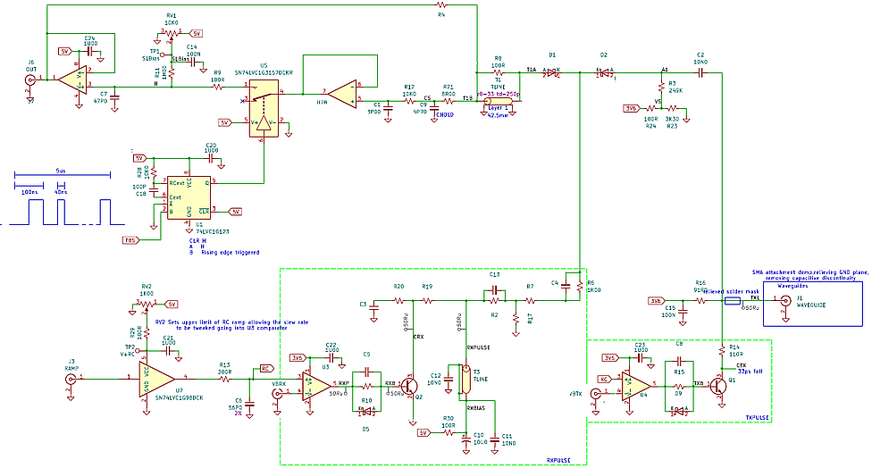
Figure 1 is a simplified schematic of the test board for the TDR01's timing, pulse generation, and sampling sections.
The Tx and Rx pulses come from LVDS receivers running off the same voltage ramp, and sharpened up by Si:Ge microwave BJTs. Their relative timing is controlled by a 16-bit DAC each, yielding better than 5-ps settability. The Tx is just a step function, so the BJT can run barefoot, but of course the Rx has to be a narrow pulse. We make this using a shorted transmission line and some RC hackery in the collector circuit of Q2. Interestingly, left to themselves the BJTs are much better at turning on [~30 ps] than turning off [~500 ns]. This is mostly fixed by a bit more hackery in their base circuits, but we still need to do all our fast measurements on the falling edges.
Figure 1: Simplified schematic of the sampler prototype for the TDR01. (The product version is MCU-controlled and doesn't have monostables or trimpots.)
Diode Sampler
The main action happens in the sampler (upper right), which consists of diodes D1 and D2 and the Rx pulse generator, plus a bit of passive support circuitry on each side. We'll talk about the Rx pulse generator in a little bit, but for now it just generates a negative-going current pulse about 80 ps wide. This current turns on both diodes, effectively making them into low-ohm resistors, and thus connecting the two sides together while the current is flowing. Because there are only two diodes and not a full bridge, current flows in only one direction during the sampling period. We handle this by setting the bias conditions carefully before the start of each time step.
The two-diode sampler has many advantages. Compared with a single diode, it greatly improves the isolation of the sampling capacitor (C9) from crap coming in from outside, such as late-time reflections from the trailing edge of the Tx pulse. This allows us to use several Tx pulses per time step without making the measurement slow, and makes the waveform easier to interpret. Compared with a four-diode bridge, as used in the famous Tektronix SD-24 sampling head, it avoids the need for (1) a very expensive matched set of diodes, and (2) precisely symmetrical sampling current pulses, one positive, one negative. It's a lot easier and cheaper to use two unmatched diodes, design around the one-way current flow, and fix the offsets in software.
One issue is that the Rx sampling pulse has to be a pretty stiff (high impedance) current source. Ideally D1 and D2 function together like a switch: signal current comes in via D2 and passes out via D1 to the sampling capacitor. In real life, during the pulse, any signal coming in via D2 will be divided. Some will follow the D1 path to the sampling capacitor, and some will get sucked into the Rx pulse generator. How much goes each way is determined by their impedances. To preserve signal and get the best waveform fidelity, we want the impedance of the current pulse to be high, and the source and load impedances (right of D2 and left of D1, respectively) to be closely similar. Because the sampler is so fast, this has to be true over a huge bandwidth (1 MHz to 8 GHz at least).
The TDR01 does this in two ways. First, the RC shaping network in the Rx pulse generator has a big (1kΩ) resistor to do most of the work, with just enough parallel capacitance to speed up the transitions. Second, the dynamic impedances seen by the short pulse are the same on both sides: near 25Ω. This happens naturally on the outboard (D2) side, but on the inboard side it's arranged using a short 33-Ω transmission line bridged by a 100-Ω resistor. And of course circuit strays and transmission-line delays have to be managed carefully to avoid trashing the pulse shapes—as the saying goes, in the picoseconds, the layout is the circuit. The 100-ohm shunt and 8-ohm series resistors make the echoes die off faster, which helps with accuracy--it's possible for a strong short-circuit (inverted polarity) reflection from sampling capacitor C9 to turn D1 on again slightly, which is bad.
All this frequency-dependent stuff has to settle out eventually, of course, but since we control the sampling, there's always enough space between pulses for that.
Sampling Loop
The design uses a sampling loop (top left), where the fast sampler's output is fed back to its input, so that at the sampling instant the two diodes ideally see exactly the same bias voltage. A little stub of transmission line on inboard diode D1 makes sure that the dynamic impedance during the sampling pulse also matches. This design is the key to the TDR01's excellent amplitude linearity. Since the design is a dedicated TDR, we can use multiple Tx pulses per time step, so that the sampling loop has a chance to converge to a stable value. For a given accuracy, there's a tradeoff between the number of pulses N and the receive pulse width. In the test board, a burst of N pulses comes in at left from a Highland Technology Model P400 4-Channel Digital Delay Generator. One channel goes to the RAMP input, the other to retriggerable monostable U1, which keeps the sampling loop closed during the burst and then stores the resulting value while the timing for the next one gets set up. (The actual TDR01 generates its own timing and controls the track/hold with a GPIO, of course.)
Ramp and Step Generators
For lowest jitter, the TDR01 uses a single ramp (lower left) to drive two LVDS line receivers to make the Tx and Rx pulses, with their relative timing set by changing the threshold levels VBTx and VBRx. Since the real instrument uses 16-bit DACs to set the thresholds, we're using a simple RC and a bit of math to get equally-spaced time steps. The line receivers work like rail-to-rail input/output (RRIO) CMOS comparators with subnanosecond edges, but are much cheaper. Their propagation delay changes a bit with threshold voltage and with the ramp slope near threshold, which needs a simple calibration during self-test. The ramp amplitude is adjustable by changing the supply voltage of buffer U7, and the two thresholds can be changed both together and separately. The actual instrument has three ramp slopes available, which adds another level of control. Varying these parameters and comparing the results with the ideal exponential ramp makes this easy.
Interestingly, the two line receivers don't talk to each other at all--there's no measurable kickout from their inputs, and no timing funnies on the Rx pulse caused by moving the Tx pulse over its full range of thresholds. That means we get the full jitter benefit without any downside.
The line receiver outputs are too slow to use by themselves, so we soup them up a bit using microwave NPN transistors running at a voltage gain of 40 or so. These are both inexpensive ($0.20) and extremely fast. In fact, one of the challenges is to keep the layout tight enough that the NPNs don't oscillate during the falling edges, which will really mess up the jitter. The Tx pulser is just that, with the right resistive voltage divider to match the 50-Ω TDR connector J1.
Receive Pulse Generator
The Tx waveform is just a step function in a 50-Ω line, but the Rx section needs a narrow current pulse to drive the sampling diodes. It's possible to differentiate the edge with a very small capacitor, but it's generally better to do it with a shorted transmission line (T3 here), which ideally gives a nice rectangular pulse whose width equals the round-trip delay to the short. We're starting with a negative-going step, so to turn it into a pulse, the short has to pull it back up again. T3's short thus has to be connected to the supply voltage, but that's pretty doable at 120 ps—the line is only ~1 cm long, so putting it over a supply pour doesn't take much area. The rest of the complicated RC network between T3 and the diodes produces a sharp, high-impedance current pulse while adequately controlling multiple reflections from T3.
The diode impedance goes inversely to the current, which in this case sharpens up the sampler response considerably; a 120-ps voltage pulse produces TDR edges of 60 ps or faster, as shown in Figure 2.
Figure 2: TDR01 trace showing the open-circuit reflection from a 60-cm RG188 SMA cable. This was taken in the 107X time-stretch mode, showing a 60-ps TDR edge (1 ps →10 μs, so 40 ps/div →400 μs/div). (For this cable, a Tektronix 11801C sampling oscilloscope with an SD-24 TDR plugin gave very similar results.)
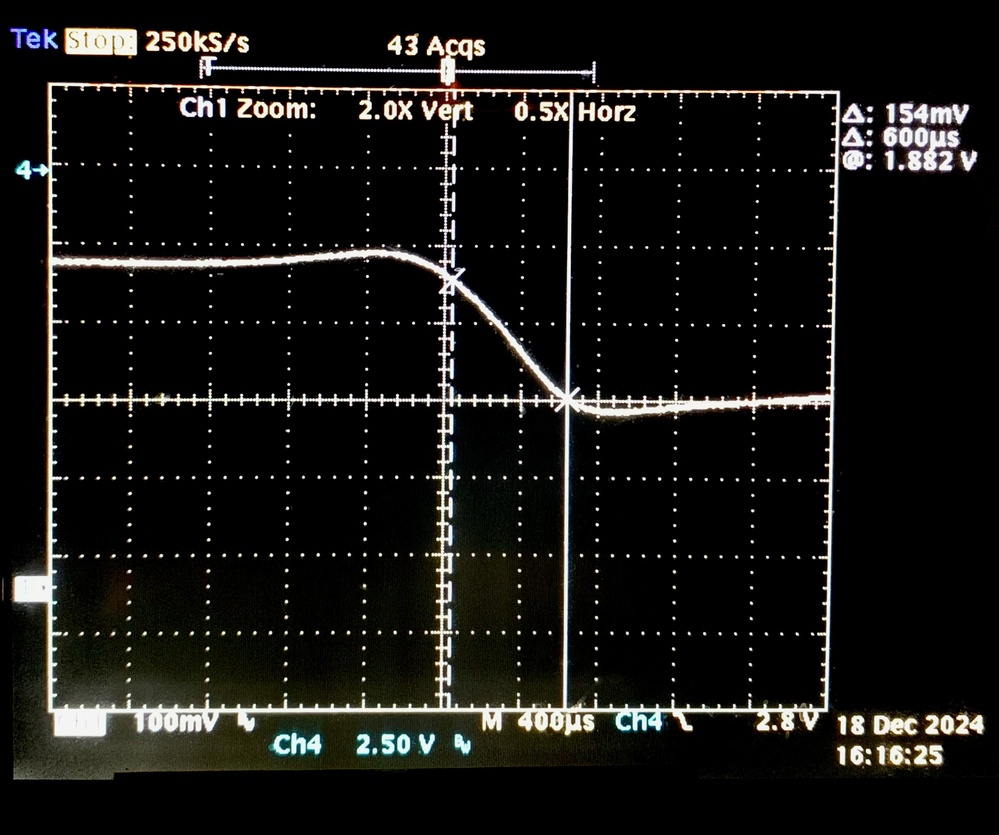
Results like this don't happen by accident—you have to watch every little thing. We used an electromagnetic simulator (ATLC2) to get the right launch conditions for the inexpensive SMA connector, because its center pin was way too large to fit on a 50-Ω trace. Before optimization, that alone was enough to trash the measurement, but after optimization, it's clean as a whistle. For more complicated things, we use OpenEMS with a bit of Python to run an optimizing loop, which is also Good Medicine.
Further Reading
Folks interested in high-speed sampling can find a lot of fascinating stuff in the patents of Agoston Agoston, who was the lead designer of the Tektronix 1180x sampling oscilloscopes. For things such as the sampling loop, see the earlier Tektronix Concepts book, Sampling Oscilloscope Circuits by John Mulvey.
Recent Posts
-
Featured Product: LA-22 Low Noise Lab Amplifier
-
 "Super-Regenerative Receivers" by J. R. Whitehead
 -
Temperature Control 1: Simple Control Theory
-
A High-Performance Time Domain Reflectometer
-
Product Announcement: QL03 Photoreceiver
Archive
2026
- January (1)
2025
2023
- May (1)
2021
- January (3)
2020
2018
2017
2015
2014
2013
2012
2011
Categories
- Design Support Consulting (8)
- Expert Witness Cases (15)
- New Technology (1)
- News (33)
- Products (4)
- SED (16)
- Sensitive Design (6)
- Ultrasensitive Instrument Design (27)
Tags
- photon budget (1)
- prototype (1)
- SEM (2)
- microscopy (1)
- microscope (1)
- product (1)
- noise (2)
- ultraquiet (1)
- thermoelectric cooler (1)
- Jim Thompson (1)
- analog-innovationscom (1)
- analog (2)
- ic design (1)
- scielectronicsdesign (1)
- website archive (1)
- MC4044 (1)
- MC1530 (1)
- SiPm (2)
- MPPC (2)
- PMT (1)
- Photomultiplier (2)
- frontend (1)
- module (2)
- hammamatsu (1)
- APD (2)
- SPAD (2)