Optics &
Photonics
—
Ultrasensitive
Instrument
Design —
Analog Electronics
The application is in a molecular probe experiment, where we're trying to measure currents of 1 nA or so in a 100-MHz bandwidth. A bit of a recreational impossibility, possibly, but cool if it turns out you can do it. (Yes, I know that 1 nA in 10 ns is 62 electrons.)
The real thing will have the pHEMT chip wire-bonded directly to the DUT, to minimize input capacitance.
The cascode design is to eliminate Miller capacitance and allow higher voltage gain, in order to swamp the second-stage noise.
The pHEMTs have drain impedances that are low and nonlinear, whereas the BFP650 has effectively infinite Early voltage, which helps the stage linearity considerably, and allows single-stage voltage gains of 30 to 50 with no problems.
The measured 1/f corner frequency of the pHEMT is around 10 MHz.
|
Noise results
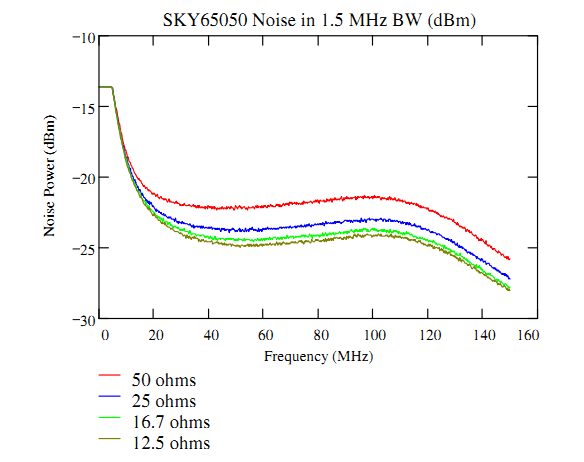
This is the measured noise of one prototype SKY65050 amplifier as a function of the shunt resistance on the input. Normally you want to keep the termination exactly constant and change the noise voltage, in order to prevent shifts in the overall gain from screwing up the measurement, but after three tries at making an adequate jig for that, I gave up and just stacked feedthrough terminations on the input. |
|
These curves show that the noise is pretty low, and the gain looks
pretty constant with source resistance. The gain is one of the
unknowns, however, so to get a noise measurement, I combined pairs
of these output noise curves, so as to cancel out the gain and the
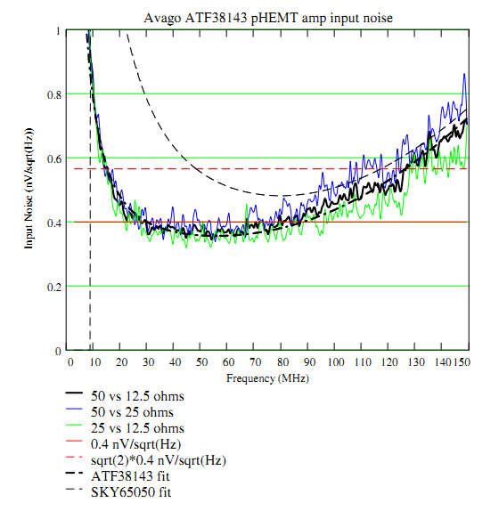
known resistor noise. The following plot shows the results for
various pairs with the ATF34143, plus fit curves for it and for the
SKY65050. The noise plots tell a consistent story, which is
encouraging.
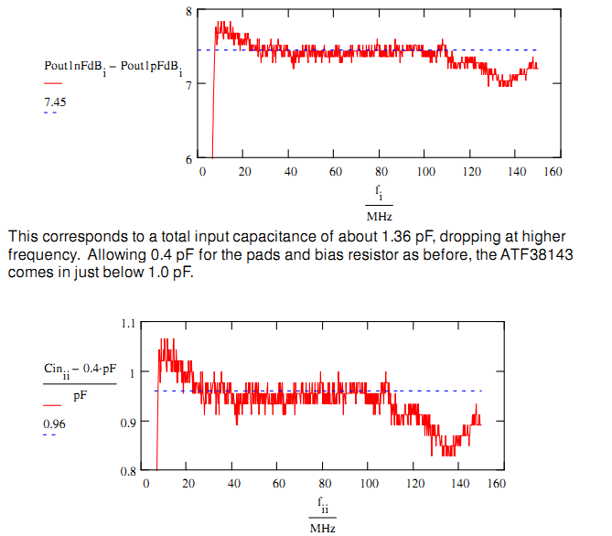
It's even more encouraging that the story is less than 0.4 nV noise and 0.96 pF input capacitance. |
|
Input Capacitance Measurements
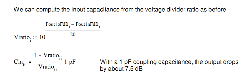
The input capacitance is computed by a sort of ju-jitsu: Using a
25-ohm source, change the input coupling capacitor from 1 nF to 1
pF, measure how much the output drops, and compute the input
capacitance from the voltage divider ratio. This works because the
input conductance is very small below about 1 GHz.
|