One problem that comes up again and again in doing measurements is that we need the apparatus to be quieter than the thing we’re measuring, ideally by at least a factor of two. Besides quiet, it should be wideband, have an accurately known gain that’s flat with frequency, have a clean step response, and generally do its job while keeping itself out of the way. There’s a wealth of detail in our app note AN-1
on photoreceiver testing.
A quick plug for a little gem of a book that all fans of early radio should know about: “Super-Regenerative Receivers” by J. R. Whitehead (Cambridge University Press, 1950). It’s part of the Modern Radio Techniques series, where a bunch of the technical movers and shakers document the advances that were made during the war, e.g. centimeter radar. This one is about the theory and practice of superregenerative radios. I learned a lot from it and had a lot of fun.
The need to control temperature is everywhere, but getting it right is more difficult than one might expect. A domestic furnace controlled by a simple thermostat keeps a house comfortable in winter, but the inside air temperature swings irregularly over a range of a few degrees. That’s fine for a house—you can have a New Year’s party, with a bunch of people dissipating a hundred watts each, doors to hot ovens and the cold outside opening and closing, no worries whatsoever. The heating system keeps it comfortable.
In a previous article, we described an ultralow-cost time-domain reflectometer (TDR) that is used as a radar dipstick for fuel gauges in heavy equipment. Its 150-ps edges were better than good enough, and its rock-bottom BOM cost ($1.30 @ 100 pcs) made it possible for the whole gauge to retail for under $40. That performance is far from the limit for low-cost samplers, as we’ll see.
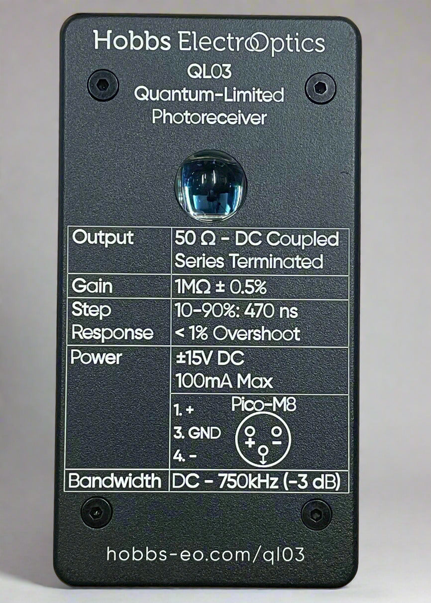
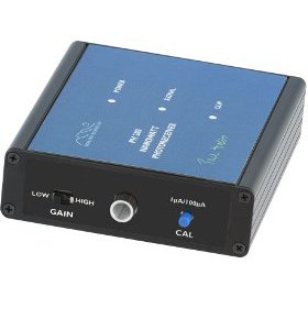
We’ve got a new photoreceiver available over at our sister site, Hobbs ElectroOptics. The QL03 Photoreceiver comes out of several proof-of-concept systems where we needed a high-sensitivity, low-noise optical receiver for low-light applications.
It features a massive 150 mm² photodiode with slight magnification from an immersion lens, making it especially effective for diffuse light measurements, spectroscopy, and fluorescence detection—plus, setup is a breeze since you’re aiming at a barn door.
One of the most enjoyable parts of electronics design is getting excellent performance with rock-bottom parts cost. The right circuit can produce exceptionally good speed, noise, and accuracy specs from very low-cost parts. A case in point was a project from December 2016: a time-domain reflectometer (TDR) for a liquid level sensing application in industry.
TDRs work by sending short pulses down a transmission line where they bounce off anything that disturbs their propagation. By measuring the time delay, you can tell how far down the line the disturbance is. It’s a bit like a one-dimensional radar, except that with TDR you can learn a lot more from the reflection than just its location. TDRs can find damaged optical fibres, waterlogged sections of coax cable, and many other things of that sort. This application used an air-dielectric coaxial probe built from two metal tubes sticking downwards into a tank, so that the first part of the probe had air as dielectric and the second part had liquid. The dielectric constant of a liquid is at least 2, whereas air’s is 1.0, so there’s a nice healthy impedance mismatch at the surface to reflect the pulse. This approach is very rugged and resistant to fouling (you can get all sorts of nameless crud in process water and diesel tanks, for instance).
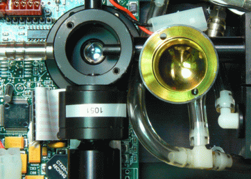
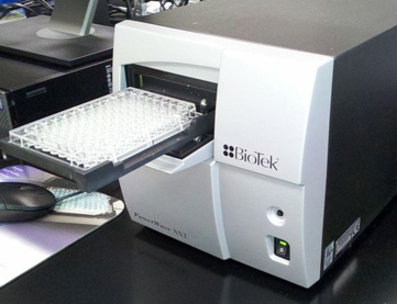
In the last year or two we’ve been doing a lot of work aimed at replacing photomultiplier tubes (PMTs) in instruments, using avalanche photodiodes (APDs) and silicon photomultipliers (SiPMs). These devices are arrays of single-photon detectors, so they’re also known as multi-pixel photon counters (MPPCs). Our main application areas include biomedical instruments such as flow cytometers and microplate readers, which have to measure low light levels very precisely but don’t need the ultralow dark current of PMTs. (Follow-on articles will talk about our SiPM work in airborne lidar and SEM cathodoluminescence, as well as on improving the performance of actual PMTs.)
In Part 1, we discussed ways to get better measurements by improving the signal to noise ratio (SNR), and saw that although it was often a win to measure more slowly and use lowpass filters, going too far actually makes things worse, because of the way noise concentrates at low frequency. Here we introduce a more sophisticated approach that generally works better: the lock-in amplifier.
We were considering a typical baseband signal, one that goes from near DC to some much higher frequency. Audio is a typical example, with a bandwidth usually quoted as 20 Hz to 20 kHz. To escape the low frequency noise, we need to move our signal up in frequency, out of baseband. In lock-in detection we make the signal periodic in time at some carrier frequency fc chosen to be several times higher than the required bandwidth. This is generally pretty easy to do, as we’ll see, and doing so ensures that none of the signal we care about remains near DC. Our noise rejection filter now needs to be a narrow bandpass centered at fc, so as to reject both low-and high-frequency noise. We’ll also need some means of measuring the amplitude and phase of the AC signal. That’s more complicated, of course, but with this setup we can narrow the bandwidth as much as we like and still get the full SNR improvement. A lock-in amplifier is a device for making such narrow-band AC measurements conveniently. It’s basically a radio that measures the phase and amplitude of its input, so that we recover a lowpass-filtered version of the baseband modulation signal that we care about, with no 1/f noise pollution to worry about. At this point we need to geek out a little bit and talk about modulation, which is what we mean by moving the signal away from baseband.
In building an ultrasensitive instrument, we’re always fighting to improve our signal-to-noise ratio (SNR). The SNR is the ratio of signal power to noise power in the measurement bandwidth, and is limited by noise in the instrument itself and the noise of any background signals, such as the shot noise of the background light or the slight hiss of a microphone.
If the signal is weak, it will have proportionally more noise, so that the apparatus has to be designed to get rid of as much noise as possible. There are a number of ways to do this. The best is to get more signal or reduce the noise, for instance by increasing the laser power and using a laser noise canceller, but eventually we hit a practical limit. At that point, we’re left with several options, all of which boil down to filtering in one form or another.
InGaAs heterojunction FETs are magic parts—fast, strong, and extremely quiet. They’re also called pseudomorphic high electron-mobility transistors (pHEMTs), because they use a 2D quantum well to to force the conduction electrons to move in a plane without much scattering. My fave Avago ATF38143 pHEMT was discontinued, but luckily Mini-Circuits stepped into the breach with their very nice SAV-551+ and its siblings, which are similar enough that the ATF SPICE model can be hacked up to work with them. (RF companies like Mini-Circuits never seem to supply SPICE models for some reason.) In one post on the ‘purpose of precision’ thread on sci.electronics.design, I noted that the Avago ATF38143 model I had posted awhile back predicted way, way too much low frequency noise. The real pHEMTs tend to have a pretty accurately 1/f PSD with corner frequencies between 10 and 50 MHz and flatband noise of around 0.3 nV/√Hz, about 10 dB quieter than the best JFETs, as well as being 20 times faster.
At EOI, we’ve been building advanced instruments for a long time. One reason for our success is our large inventory of working designs, and another is the way we go about doing it. This post walks through a typical sort of development plan for a challenging customer requirement, in the form of a hypothetical email proposal outline for a fibre-coupled noninvasive glucose sensor similar to the one we did in 2013. (You can also read about a recent project that went a lot like this, except with a single prototype stage.)
In How We Work, we gave an overview of how we build instruments, from the initial feasibility calculation (or photon budget) to delivery of the first production units.
Each project is different, of course, but there are common themes. Here’s a description of these steps from our most recent one at this writing (late January 2020), which is a low-cost cathodoluminescence detection system for use in scanning electron microscopes (SEMs).
Photon Budget
Cathodoluminescence Principles
A SEM works by scanning a tightly-focused beam of high-energy electrons (1 keV - 30 keV) across a sample, and looking at the stuff that comes out. For ordinary imaging you usually look at backscattered and secondary electrons, but there are other modes. For instance, you can get a lot of information about the sample’s chemical composition by looking at the x-rays it emits. Most samples will also emit some amount of light, a process called cathodoluminescence .
Here at EOI we have three main kinds of project. One is our internal technology development projects. Some of these fail, mostly because they tend to be insanely hard, but the ones that pay off give us important new capabilities.
The second is research projects with customers, trying to push technological limits in fields such as biochip DNA sequencing, nanoantennas for infrared detection, ultrahigh resolution optical microscopy, hypersonic lidar, and (closer to home) infrared remote controls for consumer electronics. Those ones are a bit sporty, but succeed more often than not.
There are widespread shortages of electronics parts at the moment, especially passives. Quoted factory lead times are 40 weeks or thereabouts, and since the industry is capacity-limited, it isn’t clear that the situation is going to get better any time soon, so everybody’s starting to panic. Given all this churn I’ve been spending an unconscionable amount of time lately finding suitable replacements for out-of-stock parts.
High value ceramic caps are the worst–their capacitance drops by at least 60% and at worst 95% at rated voltage, so finding an adequate substitute involves a lot more than the package, value and voltage rating. Most of their data sheets are useless, which is frustrating. However, all is not lost: most makers have websites where you can look at the C(V) curves.
From the cutting room floor at Building Electro-Optical Systems, Third Edition:
Photographic Film Okay, okay. Photographic film isn’t a detector of the sort we’ve been discussing. Film is so out of fashion, so inconvenient. It needs messy chemicals. Getting it to be highly sensitive requires all sorts of 1960s alchemy such as pre-flashing and hypersensitizing in a forming gas or hot hydrogen atmosphere. Why do we care about it at all, in these days of 4k x 4k CMOS imagers?
This was a patent and trade secret case concerning lidar (laser radar) technology for self-driving cars and trucks. It was the biggest case I’ve worked on, with potential damages over $2 billion, and also one of the most fun. I was the defendant’s expert on the patent side, and we beat Google–they dropped all their patent assertions. (This was made a lot easier by the fact that Uber wasn’t infringing, of course.)
Thanks to the efforts of our newest member, Simon Hobbs, we have a new web site with a new look and lots of new content, with more to come. We hope you enjoy it!
In the spring of 2017, I was approached by lawyers from two technology companies working in civil avionics (instruments for airplanes). I can’t say who they were due to NDA restrictions, but the job was an unusual and interesting one. The two companies had been joint development partners, but the relationship had soured and trust had now broken down completely. Both were concerned that the other was misusing intellectual property disclosed during the joint venture, and they asked me to do do an audit to see whether this was in fact true. The situation was made more complicated because one company was several hundred times as large as the other, and of course there was no court-ordered discovery and no one was under oath.
Sometimes the expert has to tell the client that their case probably won’t hold up. This case was an excellent example: University of Cincinnati v. Crayola, Inc.
As happens so often, the defendant had petitioned for a reexamination of the asserted patent, and I was asked by the plaintiff to help out. The patent-in-suit was a division of an older case, so the specification had a lot of good inventive stuff in it, but the actual claims of this patent concerned ultraviolet-activated fluorescent displays (the black-light ones you see in bars and restaurants that you write on with a fluorescent marker). An interesting idea, for sure, but one that has been in wide use since the 1960s at least.
Here I was a testifying expert working with the plaintiff in a case involving the fancy voice-coil electromagnetic actuators that control tracking and focus in optical disc drives (CD, DVD, BluRay). I did a lot of reverse engineering, including driving the actuators and taking video showing their operation, unwinding the coils to show their winding pattern and connections, that sort of thing. The case was stayed for quite awhile and then settled, so full reports and testimony weren’t required.
I’m testifying in my first trial, as an expert witness on the trade secret side of a complicated lawsuit alleging patent infringement, trade secret misappropriation, among other things. As a technical expert, I have to sit through the whole three-week trial to make sure I don’t miss any relevant testimony, even though I’ll probably be on the stand for no more than three or four hours. It’s actually pretty interesting.
Coherent laser radar (often miscalled lidar) is an ultrasensitive method for measurement of distance and radial velocity. It uses low power CW lasers and has excellent resistance to ambient light and interference from other laser radars. I’m doing a design for a unit suitable for vehicles and small ships (e.g. tugboats).
This is a very exciting development, in cooperation with a semiconductor equipment manufacturer, I’m building a visible-light scanning microscope with six times higher lateral resolution than is possible with a normal microscope. It’s based on my Ph.D. thesis work and some things I did at IBM long ago.
Sometimes you just get blindsided. Back in the mid-1960s, shortly after the laser was invented, a couple of smart guys named Norman Wild and Paul Leavy were working for a defense contractor in New Hampshire called Sanders Associates (now part of BAE Systems). They came up with a clever idea for spotting snipers on a battlefield, based on a laser and a special property of the eye. Most of us have seen the way a cat’s eyes seem to glow in the dark: their retinas are retroreflectors much like a bicycle reflector or a safety vest, that send light back preferentially the way it came. Human retinas do that too, though not quite as obviously. (Before smart digital cameras, photos taken with direct flash tended to show people’s eyes glowing bright red for this reason.)
Based in large part on my expert reports and reverse engineering of accused products, our Motion for Summary Judgment was granted. In the order, Judge Beverly O’Connell stated that the defendant “…has shown that Plaintiff has failed to produce evidence to support his claims for patent infringement.”
This is especially satisfying to me, since although I had been retained only in September, the case had been dragging on for over six years, and a previous motion for summary judgment had been denied. (The only drawback is that I had been looking forward to testifying in January.)
Three interesting new engineering projects have come in: a microplate reader subsystem for water quality assays; a sensor front end with very stringent size, weight, and power (SWaP) constraints; and a scanning microscopy development system.
After almost exactly three years waiting for a claim construction ruling, this case has gotten started again. I’m working on the trade secret side of a complicated suit arising out of a contemplated acquisition that wasn’t completed.
A case I’ve been working on since March 2012, DCG Systems v Checkpoint Technologies, has settled, and I’ve been retained in two others, ThinkOptics v Nintendo et al. (helping ThinkOptics with an inter partes reexamination), and Voxpath RS v Desay et al. (defending Samsung in an optical disc case).
I’m designing two brand new front ends for a scanning surface voltage tool for semiconductor manufacturing. Normally there are two ways you can measure surface potential—the vibrating Kelvin probe, which gets you the actual voltage but is very slow, or the fast-scan method, which is fast but gets you only the 1-D derivative of the potential.
Working with a leading semiconductor tool vendor, I’ve come up with both an improved transimpedance front end and (more interestingly) a new class of front end amplifiers that should be able to get the actual voltage like the Kelvin probe while going fast like the scanning method, while providing at least 15 dB SNR improvement over either one.
(We can’t show ours due to NDA requirements– this is a cool one from Brown University that uses plasmonics.)
We’ve just started a collaboration with a prominent biotech company in California on spectroscopic-detection biochips using photonic waveguides. Our part of the effort is to explore the design space and come up with new topologies to maximize signal-to-noise ratio and measurement stability. This is an excellent application for POEMS as well as being an exciting new area for us.
Besides info on do-it-yourself photoreceivers, I am introducing a new line of electro-optical products in cooperation with Highland Technology, a cutting-edge instruments company in San Francisco. The first product is a shot noise limited free space photoreceiver with quantum-limited sensitivity from 60 nW to 100 μW and an honest 1 MHz bandwidth (3 MHz on the 100 μW range). For photocurrents below a microamp, it’s significantly better than even the bootstrapped cascode, and it comes in a nice module that fits your setup easily and has normal normal 1/4-20 and M6 threaded mounting holes.